PRINCIPLE
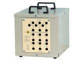
Our primary zig-zag transformer comprises three windings, whereas the secondary one comprises six half-windings. All of these windings are galvanically isolated from each other. Students practise wiring the primary
winding into a star or delta, and the secondary winding into a star, delta or zig-zag. In total, this is six schematics: Yy , Yd , Yz , Dy , Dd , Dz.
The coils are designed in such a way that the voltage outputs always correspond to the 230/400V standard. The section of the wire is calculated in such a way that the rated power in the secondary is available regardless of the connection schematic used.
Interconnections are made using safety cables, directly on the terminal board. The following are symbolised on the terminal board:
• the coils
• with a point, the direction of the coil
• with upper case letter, the terminals of the primary transformer
• with lower case letters, the terminals of the secondary transformer.
• the safety conductor
Comprehensive instructions with Fresnel diagrams explain how the combination of coils alters the phase-to-ground and composite voltages. They explain how to determine the time index.
A method shows how to find out the direction of the coils in an unmarked zig-zag transformer.
Power:
Secondary: 1000VA
Primary : 3 x 230V separate.
Couplings modify the voltage at the secondary Secondary : 6 x 115V or 6 x 133V according the coupling at the primary
Properties
- ZIG11/ELE

