EDUCATIONAL OBJECTIVES
• Understanding of the regulation principles by PID, from theory to practice.
• Wiring, calibration, loop measuring, statement of curves.
Practical works
• Wiring of a measuring loop according the standard 4-20mA with Pt100 probe and transmitter
• Calibration of the converter Pt100 / 4-20mA with the help of a decade box (not supply)
• Establishing a calibration sheet, drawing the calibration curve
• Identifying and testing of a Pt100 probe. Calculation of the current through the Pt100 probe.
• Measuring of a loop current without opening the loop
• Using a 4-20mA calibrator
• Establishing the functional diagram and determining the role of different components
• Establishing the loop diagram of regulation and the wireline diagram
• Identifying the controlled value, the monitoring value, the disturbance values.
• Determining the direction of action of the regulator, according to the direction of the process and
the direction of the correction member
• Determining the static characteristics of the process (static gain, timeout, time constant) in order to
calculate the transfer function
• Determining the oscillations period and the gain of the critical loop, the integration factor.
Determining using models Broida and Pessen correctors P, I and D
• Viewing of the response curves with 3 correctors: P, I and D
• Adjusting of the PID correctors and testing according two methods: enslavement and regulation
• Testing of different empirical methods for adjusting PID correctors
• Troubleshooting training by fault simulation
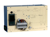
This small oven, where an air stream is used to bring the parts to the correct temperature, is equipped
with PID to control the temperature accurately to within a tenth of a degree. The DESP model uses
only industrial components. The PID control system - 4-20mA standard for measuring input and output
- controls air stream temperature. To prevent any risk of burning, oven power has been limited
to 250W and air temperature to 100°C. The student wires the Pt100 3-wire probe, 4-20mA measuring
loop, 4-20mA control loop, temperature transmitter, and loop power supply to the terminal
strip. Current is measured at the conversion resistance using a multimeter, without opening the loops.
Maximum accessible voltage (without dismantling the apparatus): 24VDC. The system operates in
two modes: automatic and control. In the latter case, an adjustable-speed fan sets up a disturbance.
The terminal strip and components are suitable for demonstrating all types of wiring errors and troubleshooting.
The temperature and thermostat control current graphs (used to determine static, loop,
and critical gains, as well as dead time, and the time constant) are produced either manually
(possible due to the slow changes in temperature), or on a PC using LOGIFOUR software (option)
and PC interface.
Properties
- DESP/ELE

