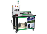
EOLYP is a test bench dealing with the study of the hyper synchronous activity of a wind turbine for its electricity production aspects, excluding the mechanical aspects.
Due to noise pollution and draughts, which are incompatible with a classroom environment, the propeller has been replaced by a variable speed drive motor.
The functional diagram presents the operating principle. The safety components placed in the electrical cabinet are not represented to simplify reading. The propeller, for which the operator adjusts the speed, drives the generator from 0 to 1800 rpm. Two sensors placed on the shaft, returns rotation speed and torque information to the console which displays this information. The generator is coupled to the public three-phase network, through an electrical measurement bench indicating the:
• active power injected into the network. • voltage between phases
• current
• power factor.
The central-zero wattmeter shows that depending on the drive speed, the generator consumes or produces energy highlighting the hypersynchronous and hyposynchronous operations. The voltage/current distortion also changes with the rotation speed as indicated by the central-zero cosφmeter. The adjustable capacitors battery is used to adjust the cosφ to around 1 depending on the speed and power produced.
COMPRISES
• 1 frame on casters, dim. 1200x750mm height : 1820mm • 1 asynchronous motor 1.5 kVA
• 1 generator
• 1 DC tachogenerator / 1 torque sensor
• 1 command console
• 1 electrical cabinet
• 1 network coupling unit
GENERATOR FEATURES
• Generator: 3x400VAC Asynchronous motor.
• Active power injected into the network: 0 to 1.2kVA • Generator efficiency: 78%
• Speed variation: 0 to 1800 rpm
ELECTRICAL CABINET
Interior:
• 30 mA circuit breakers and magnetothermal and thermal circuit breakers. • 2.2kVA speed controller with control unit on the console.
• stepped capacitors battery
On the front:
• 1 emergency stop circuit breaker
• 1 switch disconnector
• 1 stop/Start button with push button
• 4 switches triggering the capacitors to rectify the cosφ
• 2 indicator lights show a thermal fault on the motor and generator

Several tutorials are delivered with the teacher and student folders:
• Plot of the active power curve as a function of the rotation speed.
• Demonstration of the reactive power injected into the network at synchronism speed.
• Compensation by the capacitors battery in hypersynchronous operation.
• Demonstration of the reactive current at maximum active power and compensation.
• Impact of the speed on the cosφ and solutions to automate the regulation.
• Efficiency calculation: Electrical power injected into the network/mechanical drive power • Checks before coupling with the network. Limit speed, electricity production peak.
Eigenschaften
- EOLYP-/ELE

