EDUCATIONAL OBJECTIVES
• Understanding and using of the method of Fourier series decomposition
• Studying of the power in presence of harmonics
• Understanding the compensation of the power factor by harmonics correction
• Studying the functioning of the dephasing dimmer
Proposed Practical Works
• Making a power balance in presence of harmonic of currents and voltage
• Observing the disturbances caused by a dimmer
• Raising the power factor, by offsetting a portion of the reactive power and filtering of harmonic of order 3
• Observing network disruptions, caused by a dimmer
• Increasing the power factor by canceling the reactive power (with an anti-resonance circuit)
• Reading the evolution of the PLC program
• Producing a summary document as a record
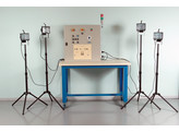
Four 500W halogen lamps on a tripod are powered by a SCR power regulator which creates harmonic pollution
and reactive power degrading the power factor.
A passive filter with an LC circuit is used for:
• minimising the third order harmonic pollution
• measuring the power factor by decreasing the reactive power
• observing the resonance phenomenon.
It is also possible to study the operation of the phase-shift of the SCR regulator.
Principle : the industrial lighting of the panel – simulated by the four halogen lamps on a tripod – varies depending
on the ambient sunlight, simulated by one low-voltage spotlight placed in the cabinet. When the current in the halogen
lamps is significantly degraded, the filtering components are activated, either manually via the switches on the front
or automatically by a PLC.
Auto mode: 3 sunlight levels are programmed. For weak sunlight the 3rd order current harmonic is high.
The PLC activates a passive filter which tends to decrease this harmonic.
Manual Mode: a potentiometer is used for continually adjusting the sunlight level. Varying it makes it possible to:
• VIEW, with the help of the network analyser (ref. 6830), the effect of the dimmer on the level of the current harmonics;
• MEASURE THE power factor by inserting a capacitor induction coil. The network analyser reveals that the solution
can be found in the induction coil.
• FILTER HARMONIC 3 by using a resonant filter which will reduce noticeably its current
THE FRONT PANEL COMPRISES
• Safety terminals for the measurements
- voltages and currents supplied by the network
- voltages and currents in the halogen lamps
- voltages and currents in the filter components
• Switches for activating or deactivating the filter components
• An Automatic/Manual mode switch
• A lighting potentiometer
OTHER FEATURES
• Light column indicating that the mains power is on
• PLC Software, tutorial and instructions for use are supplied.
• Power supply: 230V 50Hz
• Cabinet: 820 x 400mm Height: 930mm
• Base with wheels, with laminated bench-top: 1200 x 750 x 970mm
• Overall dimensions: 1200 x 750mm Height: 1900mm - Weight: 128kg
Eigenschappen
- HARMO-35/ELE

